In this post, I will explain how to know the total capacitance of a circuit.
As you know, capacitors look like resistors, could be connected in parallel or in series. To calculate the total capacitance, you have to know this two formulas:
- In series:
- In parallel:
Example
Calculate the total capacitance of the circuit.
Well, if you can see, the resistors are connected in parallel, so we only need to do 1 formula
Ct= C1 + C2 + C3
Ct= 0.1+0.2+0.3
Ct= 0.6 uF
Alejandro Iglesias Prieto; NSI
jueves, 1 de marzo de 2012
Resistors, color code
I will explain how to know the value of the resistance of a resistor with color code.
A resistor is an electronic component that regulates the flow of electrical current in an electronic circuit.
In this photo you can see a resistor. As you can see, in the non-metal part (in this case wood) there's four colored bands painted. Each band has a meaning:
- First band is the first number on the left.
- Second band is the second number on the right
- Third band represents de number of zeros on the right
- Fourth band is the tolerance of the resistor.
Here is a table that explain the color code and their value:
Example: Calculate the resistance of the resistor showed in the first photo.
- First color is brown, so first number is 1
- Second color is black, so second number is 0
- Third color is green, so it has 10^5 zeros
- Fourth color is gold, so it's tolerance is +-5
So, the resistance is 1000000 ohms = 1000 kiloohms
Parallel and series connections
Here, I will explain how the resistors could be connected and how much is the total resistance of a circuit.
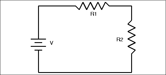
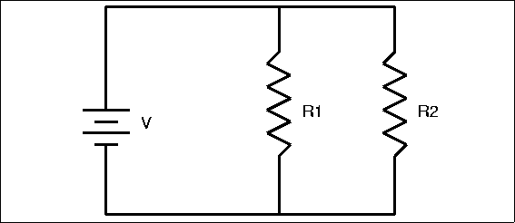
There are two types of connections:
- In series:
You could calculate how much is the total resistance of a circuit with the resistors connected in series with this formula:
- In parallel:
Ohm's law
Here, I will explain how to calculate the current by two types:
- Ohm's law:
- Multimeter:
You also can measure the current of a circuit with the multimeter. You have to put the roulete in the section of Amperes and it's like measuring voltage.
- Ohm's law:
Here's the Ohm's law, I is the current (amperes), then V is the voltage (volts) and R is the resistance (ohms).
If you would know the value of the current of your circuit, you only need to calculate through Ohm's law.
Example:
You have a circuit connected with 20 volts and two resistors in series with 1 Kiloohm each. How much is the current?
You also can measure the current of a circuit with the multimeter. You have to put the roulete in the section of Amperes and it's like measuring voltage.
Measuring the voltage
In this first post, I will explain how to measure the voltage of a circuit with the multimeter.
Firstly, you need a stripboard, some resistors or wires, crocodile clamps for connect the circuit with current and the multimeter.
Your circuit must be like this:
When you have your circuit buildt, you must connect it with current through crocodile clamps hooked at the resistors. Then you have to adjust the multimeter, for example, if you give 10 volts to he circuit, you have to put the roulette in 20 V, in the nearest higer value of your voltage. After that, you have to measure the voltage puting the connector meters of the multimeter on a resistor (on the metal part).
And that's all.
Firstly, you need a stripboard, some resistors or wires, crocodile clamps for connect the circuit with current and the multimeter.
When you have your circuit buildt, you must connect it with current through crocodile clamps hooked at the resistors. Then you have to adjust the multimeter, for example, if you give 10 volts to he circuit, you have to put the roulette in 20 V, in the nearest higer value of your voltage. After that, you have to measure the voltage puting the connector meters of the multimeter on a resistor (on the metal part).
And that's all.
Suscribirse a:
Comentarios (Atom)


